

Typically after the relays click a few times, the TV will eventually come on. However in time the relays will need to click on and off more and more times before the TV will come on... and eventually the TV will likely just cycle the relays over and over and it will never come on.
If you just want the instructions on how to do this repair, skip to step 1 below. If you want my personal saga explaining why I decided to perform this repair myself... read on.
In my case, I have experienced this failure on two separate occasions. I originally bought this TV back in 2008, and sometime within the first year I began to hear the dreaded clicking relays suggesting there was a problem. About a week after this started I was watching TV one evening and all of the sudden it sounded like a firecracker went off inside of the TV. From experience I knew this meant a capacitor most likely blew up... however since the TV was still under warranty I wasn't about to crack it open to investigate.
I placed a call to Samsung and started the saga of getting the TV repaired. Long story short the process involved at least half a dozen calls, several weeks of waiting for parts and a technician, and having to take a day off of work to be around when the service tech actually showed up. Did I mention that the TV failed about a week before the Superbowl and there was no way to get it fixed before the game? Yea... perfect timing.
Eventually the technician showed up and as soon as he opened the back of the TV and removed the shield from the circuit board it was very obvious which capacitors had blown. The technician removed and replaced the power supply board with an updated version, and then closed the TV up at which time we tested it and verified it was working as good as new.
That was early 2009... and up until a few weeks ago the TV worked fine. However around two weeks ago I noticed when the TV was powered up the red LED on the front seemed to blink several times before it would power up. Then a few days after that, the dreaded clicking relays started. As the days progressed it took longer and longer for the TV to power up and it became obvious it was only days away from another total failure.
I did a bit of research and discovered I wasn't alone. In fact many users of this particular model of television (the Samsung LNT4661F 46 inch LCD HDTV) had experienced the same symptoms, and it all boiled down to bad capacitors. It seemed there were a few ways to fix it... the easiest of which is to simply replace the power supply board. However with a little bit of electronics knowledge and some replacement capacitors... it is much less expensive to simply replace the bad capacitors rather than bearing the expense of the entire circuit board.
Therefore in order to verify the issue I removed the back of the TV along with the metal shielding that covers the power supply board and with a little inspection it was very obvious which capacitors were failing. As you can see from the image below, two of the capacitors show signs of failure and are bulging. One of them was even showing a crack on the top which means it was probably days before a total failure.

Reading the specs from the side of the capacitors showed that they were 10V caps rated at 2200uF and had a max operating temperature specification of 105°C. In my case it was only these two capacitors that were failing, however others have reported that the 1000uF capacitors directly beside the 2200uF caps had also failed.
In any case, now that I knew what the source of the issue was, I decided it was time to order some replacements. However based upon markings on the board as well as information I had found online, it seems 10V capacitors are simply too small which is what contributed to the premature failure. It appears this particular circuit was designed for 12V capacitors yet Samsung decided to use 10V caps instead. It stands to reason why they wouldn't last. Therefore, in order to prevent this from happening again I opted to replace the caps with 16V capacitors, but others have used 24V or even 50V replacements... it is just a matter of what is available. A higher voltage capacitor doesn't mean it will run at a higher voltage... merely that it is capable of handling that voltage. In this case, having a little extra buffer was a good thing as the caps would be running at a voltage well under spec.
It just so happens a friend of mine was in the process ordering some parts for himself, so he just added a few of the capacitors to his order and they were on the way. In the meantime, it was time to get started removing the old capacitors and prepping the board for the replacements.
Step 1: Remove the power supply board. Ok so technically step 1 would be remove the back of the TV and then remove the shield covering the board itself... but if you can't figure that part out on your own you probably shouldn't even attempt to replace the capacitors yourself.
To remove the board, you will want to disconnect all of the various connectors that run into the board and then remove the six screws that hold the board down to the mounting plate / chassis. It isn't a bad idea to take a photo to ensure you get all of the connectors in the right places upon re-installation (or just use my photo as a guide). The capacitors being replaced are shown at the upper right hand corner of this board.

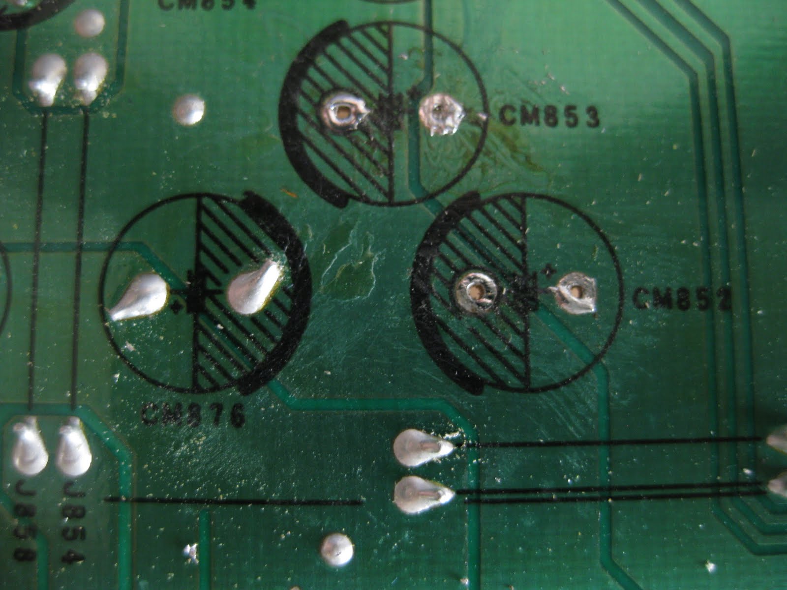
Step 2: Desolder the old capacitors. In my case, this involved CM852 and CM853. You can see from the image below what the top of the board looks like after the capacitors have been removed. I won't go into great detail here about how to actually desolder these since it is assumed if you are attempting this you have some basic knowledge on how to use a soldering iron, but it is helpful to have some desoldering braid and/or a solder sucker (desoldering pump) to remove the old solder as you heat up the leads.

And this is what the bottom of the board looks like after the capacitors have been removed. Note that there are polarity markings on both sides of the board. Try not to apply too much heat to the board as you don't want to inadvertently harm the solder traces on the board.
Step 3: Paying attention to the polarity of the capacitors (the shaded area of the board corresponds to the negative lead of the capacitor), insert the leads of the replacement capacitors through the holes in the circuit board and bend them outward to hold the capacitors tight against the board. Apply heat to each lead and solder them in place.

Step 4: Using a side cutters, trim the leads of the capacitors. Some may prefer to cut the leads prior to soldering, but I prefer to do so after they are soldered in place just in case I need to make any adjustments. After trimming, verify the solder joints are intact and are solid. The image below shows the end result from the bottom of the board.

And this is what the new capacitors look like from the top of the board. The new caps were slightly larger than the originals, but they fit just fine.

Here is another side angle showing the new capacitors in place. Several of the other original caps (the lighter blue caps in the image) may also need to be replaced if they show signs of failure, but in my case they all appear ok.

Step 5: Reinstall the power supply board back into the TV chassis. Tighten all six mounting screws, and ensure all of the various connectors are reconnected properly. Once everything looks ok, reinstall the metal shield that covers the power supply board as shown in the image below.
If there is any doubt about the location of the various connectors... simply refer to the image in step 1 above. However aside from forgetting to actually install one, it is nearly impossible to do this step incorrectly since aside from the two in the lower left corner, all of the connectors are unique.

Step 6: Reattach the back of the TV, install the stand and/or wall mount cover plate... connect the TV to a video source, plug it in, power it up and enjoy!
 |
| Step-Brothers Anyone? |
The replacement capacitors cost under a buck each plus a few bucks for shipping, so the end result was a repair for around $5. I had the soldering iron, soldering braid, and solder on hand already so there was no additional cost there. Total time from start to finish (not counting the time I was awaiting parts delivery) was approximately 20 minutes.
Considering the cost for a technician to come out and replace the board could easily top $300... I think this repair is more than worth it. With a little luck the third time will be a charm so hopefully I won't need to do this again!
If you found this post helpful, or if you have any questions about the process, please leave a comment and let me know.